Connect all the input, output and sense (if equipped) wires together. Install load cell in position 2.

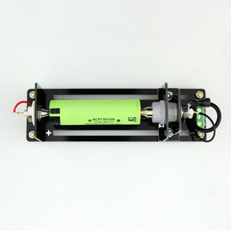
4 Wire Battery Resistance Capacity Test Testing Stand Cell
Due to no nay compensation of cable resistance change effect.

How to test a 6 wire load cell. Load the load cell between 50% to 100% of its capacity for 5 seconds. Cut off working power supply and disassemble the output & input wire of the load cell one by one. The procedure is as follows:
It has proven to be flexible, reliable, accurate, linear, and cost effective. It is also the least understood, and many users make simple wiring errors, causing excessive noise, and in extreme cases, damage to the sensor and instrument. Set the multimeter in dc millivolts and connect the output wires of the load cell to the multimeter.
1.3 checks when load cell is connected to monitor when installing a load cell system the usual installation procedure would be: Now, test the load cell step by step as follows: Measurement is truly continuous, and sft resolution is over 1:8'000'000 in 20 ms.
Make sure it is within the allowed tolerance. Remove the load and check if the mv/v output returns to the allowed tolerance. Connect the load cell to a stable power supply and measure the mv/v output like the step before.
Insulation resistance insulation resistance is measured between the cable shield and the load cell circuit. The rocker column is designed so that it will return to an upright position after the deck has been disturbed laterally, eliminating the need for check rods. Divide the reading value by the input or excitation voltage to get a zero balance reading in mv/v.
All these measures do not. The sense wires of the 6 wire load cell can be connected to the sense terminals of the weight indicator to measure and adjust the amplifier on the actual voltage of the load cells. Using the digital multimeter, measure across the signal wires.
Then measure the insulation resistance between the connected wires and the cable shield. When connecting a 6 wire load to a 4 wire system, the sense wires should be connected to the same place as the input wires. The multimeter will register a change in voltage measured across the load cell's output.
If load cell and indicator distance is short then used this type of load cell. First, disconnect the load cell from the summing box and indicator panel. Weighing scale with 4 wire load cell is less stable.
Supply a voltage of 5v or 9v dc at the excitation leads and place a test weight on the load cell. How to test a load cell Likely cause is a damaged or faulty load cell or incorrect/faulty wiring.
Connect excitation and signal wires to monitor 3. Disconnect the summed signal wires from the instrument (leave the supply [excitation] wires connected). All of these cells are used in vehicle scales.
If not, you have a damaged load cell. If the multimeter shows that the output and input impedance, the insulation performances of signal cable and shielding layer decline (generally impedance ≥5000mω), this load cell can be judged to have a fault. There are a number of mechanical and/or electrical failures that can cause errors in load cell weighing systems.
The load cell is placed between the retaining wall and the hydraulic jack. The first test would be to measure the sum (combined value) of the load cell outputs, at the junction box and at the input to the instrumentation. That reading should match the original load cell calibration certificate or the product's datasheet.
Generally, load cell manufacturers would provide detailed input/output impedance, insulation impedance, zero output, output sensitivity and correct wiring code identification. Measured value resistance between exc+ and sense +lines Fortunately, most issues can be found with a few basic tests which are detailed below on how to troubleshoot a load cell.
Zero output refers to the output value of load cell without load. Dataq.com sells affordable units that work admirably for data collection of hobby rocket motors performance.

Pneumatic Actuator Seal Pressure Interface

4 Wire Battery Resistance Capacity Test Testing Stand Cell

Dimensional Calibration UMT Calibration Laboratory

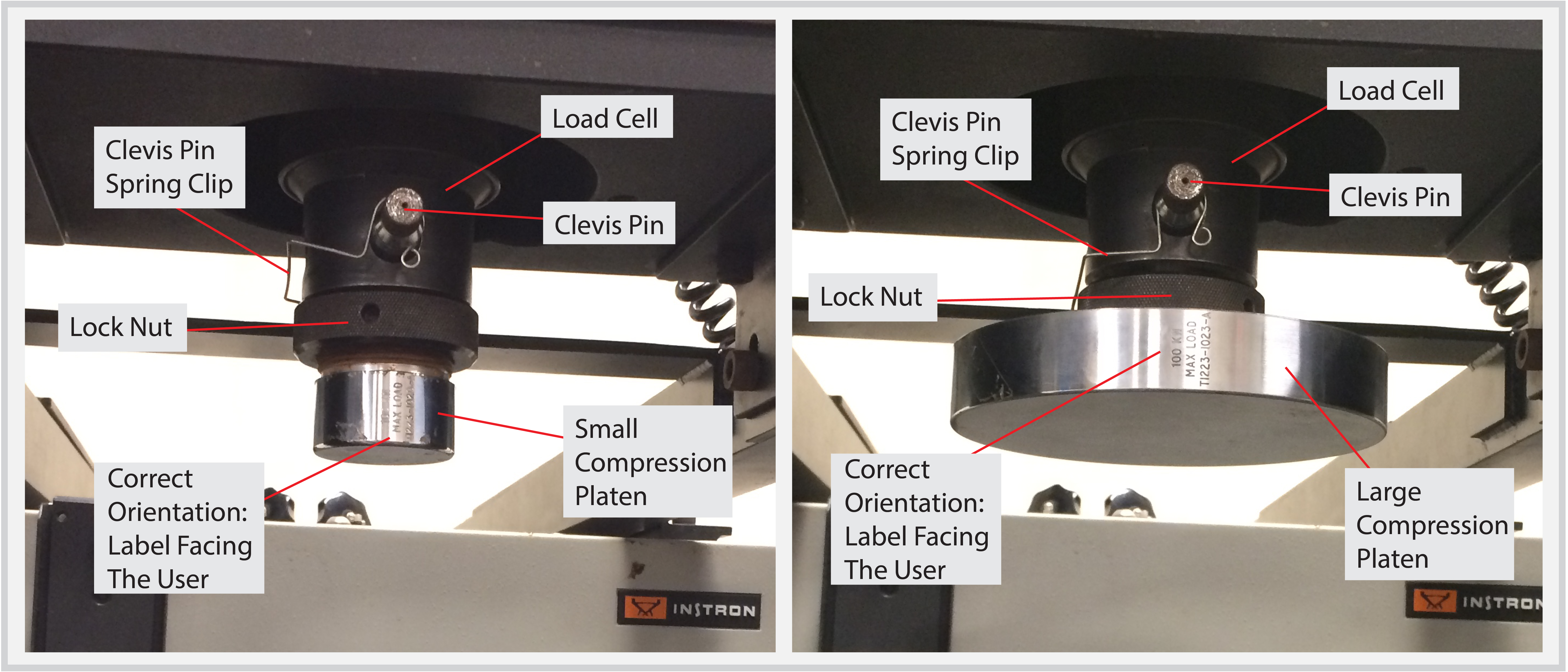
Experimental test setup for dynamic uniaxial compression

Digitale Load Cell Gewicht Sensor 1 KG Draagbare

Loading Measuring Shackle Load Cell For Stage Buy Load

6wire load cell substitutes for hbm load cell z6fd1
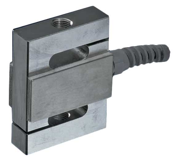
SBeam Load Cell Tension & Compression Model TC01

Experimental test setup for dynamic uniaxial compression
Instron Load Cell Wiring Diagram Wiring Diagram
Load cell?? YouTube

load cell checking with multimeter 6 wire load cell YouTube

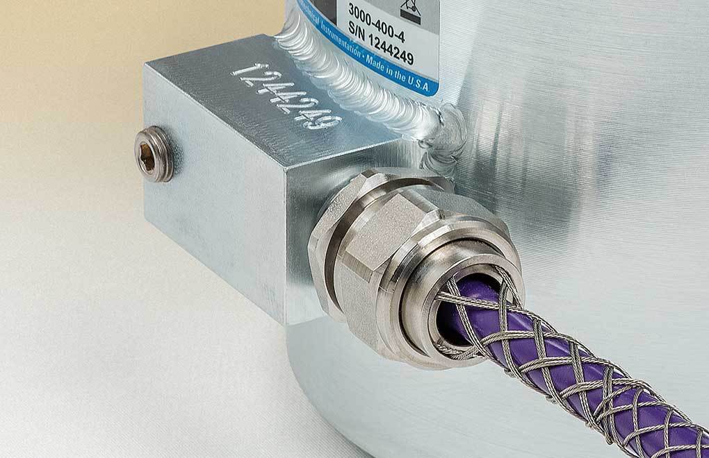
Compression load cell F1211 WIKA USA
VW Load Cells BDI Structural Testing & Monitoring Systems

4 Wire Load Cell Wiring Diagram

5Kg Load Cell With HX711 Module • Make Electronics

4 Wire Battery Resistance Capacity Test Testing Stand Cell

Dimensional Calibration UMT Calibration Laboratory
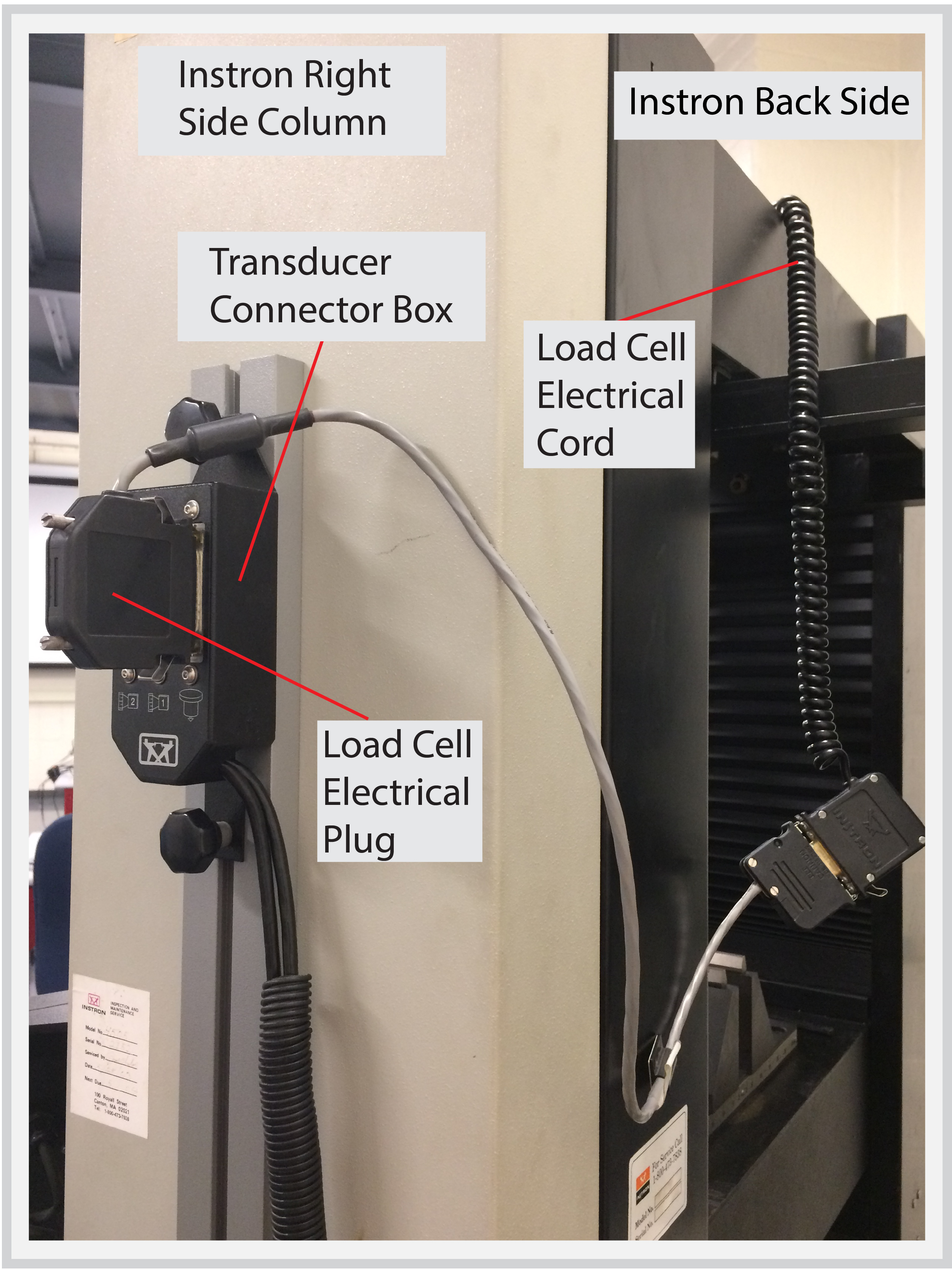
Instron Load Cell Wiring Diagram Wiring Diagram